
We specialize in high-end testing solutions for aerospace, defense, marine and nuclear sectors. Seeking opportunities in emerging markets, we offer comprehensive test benches for aircraft engines, including integrated compressor/turbine testing, high-speed rotor dynamics with balancing,casing fatigue simulation,bearing/sealing, generator,semi-physical fuel control tests, and a dual-purpose stand for component & combustion R&D. Our offerings also cover liquid rocket engine test benches for turbine integration,bearing/sealing modifications, and water pump validation. Additionally, we test helicopter gearboxes (MGB, IGB, TGB) for load,vibration and durability. Committed to tailored solutions,we drive innovation in global aerospace and defense.
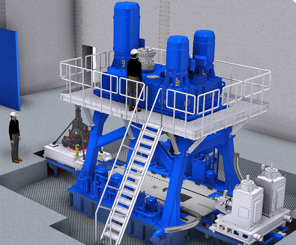
The test bench integrates a high-speed dynamic balancing machine with a rotor dynamics test bench, driving the aero-engine rotor to rotate at high speed via a motor or simulated power source. It eliminates vibrations caused by uneven mass distribution through dynamic balancing calibration, preventing bearing wear, structural fatigue, or even total engine failure due to imbalance. This provides data support for design improvements, shortens the R&D cycle, and ensures the safe operation of aero-engines throughout their lifecycle.
The high-speed generator test bench for aero-engines is mainly used for performance testing and reliability verification of supporting generators. It drives the generator to rotate at high speed through a motor or a power source simulating the aero-engine, mimicking its actual operating conditions in the aero-engine.It detects whether key performance indicators such as power generation efficiency and voltage stability of the generator under high-speed operation meet the power supply requirements of aero-engines, ensures the dynamic matching between the generator and aero-engine, provides data support for design improvements, and guarantees the safe and reliable operation of the aviation power supply system.
By installing the compressor and turbine on the same test bench, simulating the actual working environment of the engine, using a power system to drive the compressor to operate and compress air, the compressed air is delivered to the turbine through pipelines to drive it to rotate. Meanwhile, various sensors and measuring devices are used to monitor the aerodynamic, mechanical, and thermodynamic parameters of both in real time. This allows verifying the matching, operational stability, and overall performance of the compressor and turbine on a unified test platform, ensuring they can work efficiently together in the engine's actual operation, and optimizing engine design, troubleshooting faults, and improving performance.
The high-speed turbine dynamometer test bench drives the turbine to run at high speed via motors, simulates actual working conditions, applies controllable loads through the dynamometer, and uses sensors to measure performance data (torque, speed, etc.) and operational data (temperature, vibration, etc.) in real time. It aims to evaluate the turbine's power output, reliability, and thermodynamic performance, detect its performance under different conditions, provide data for design optimization and quality inspection, and ensure stable operation in aerospace and energy sectors.
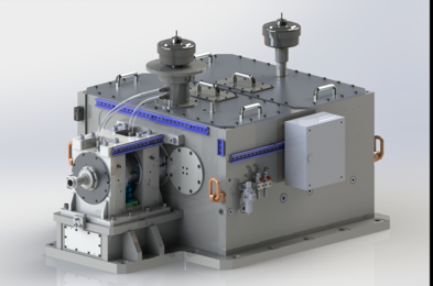
The helicopter main gearbox test bench uses motors to simulate engine power input into the main gearbox, which is transmitted through drive devices. The loading system simulates loads from rotor blades and other components under different working conditions, applying corresponding resistance torques. Various sensors (torque, speed, temperature, vibration) collect real-time data on transmission efficiency, temperature rise, vibration, etc., under different speeds and loads. The control system adjusts power, loading, and data collection, sending data to the processing system for analysis to evaluate the gearbox's performance, reliability, and durability, verifying compliance with design standards.
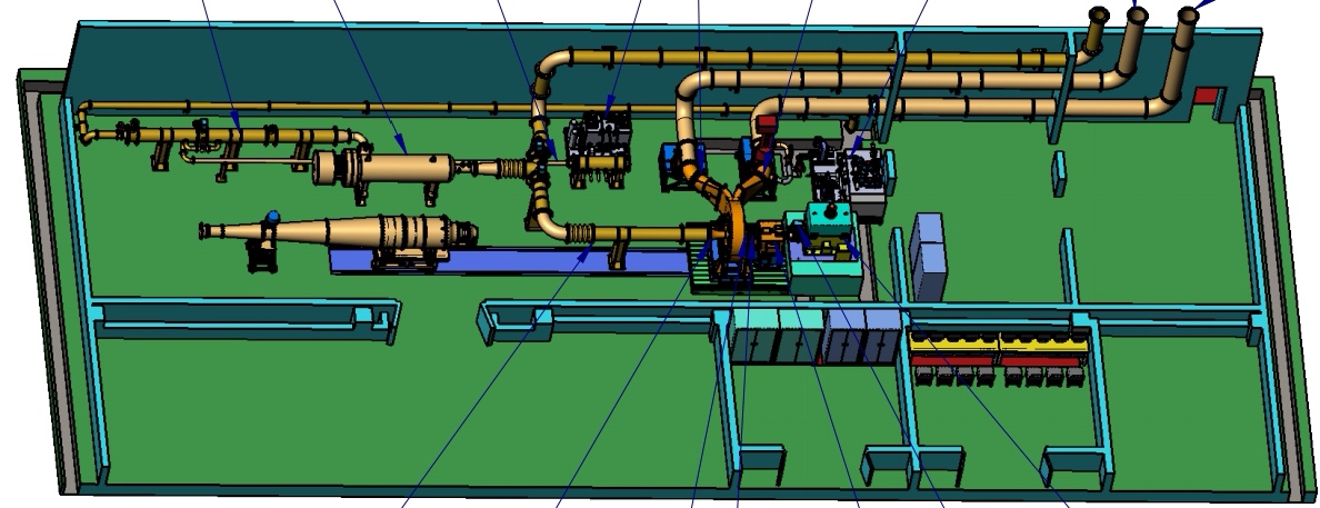
The aero-engine testing system simulates different working conditions on the ground and in flight, such as air pressure and temperature, and drives the engine to operate via driving devices. High-precision sensors are used to collect key parameters in real time, including speed, temperature, and pressure. The loading system simulates flight loads and applies controllable loads. Collected data is preprocessed and transmitted to the analysis system, where it is compared with standard parameters to evaluate the engine's performance, reliability, and durability, determine compliance with standards, and provide data support for R&D, maintenance, and fault diagnosis.
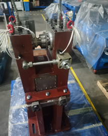
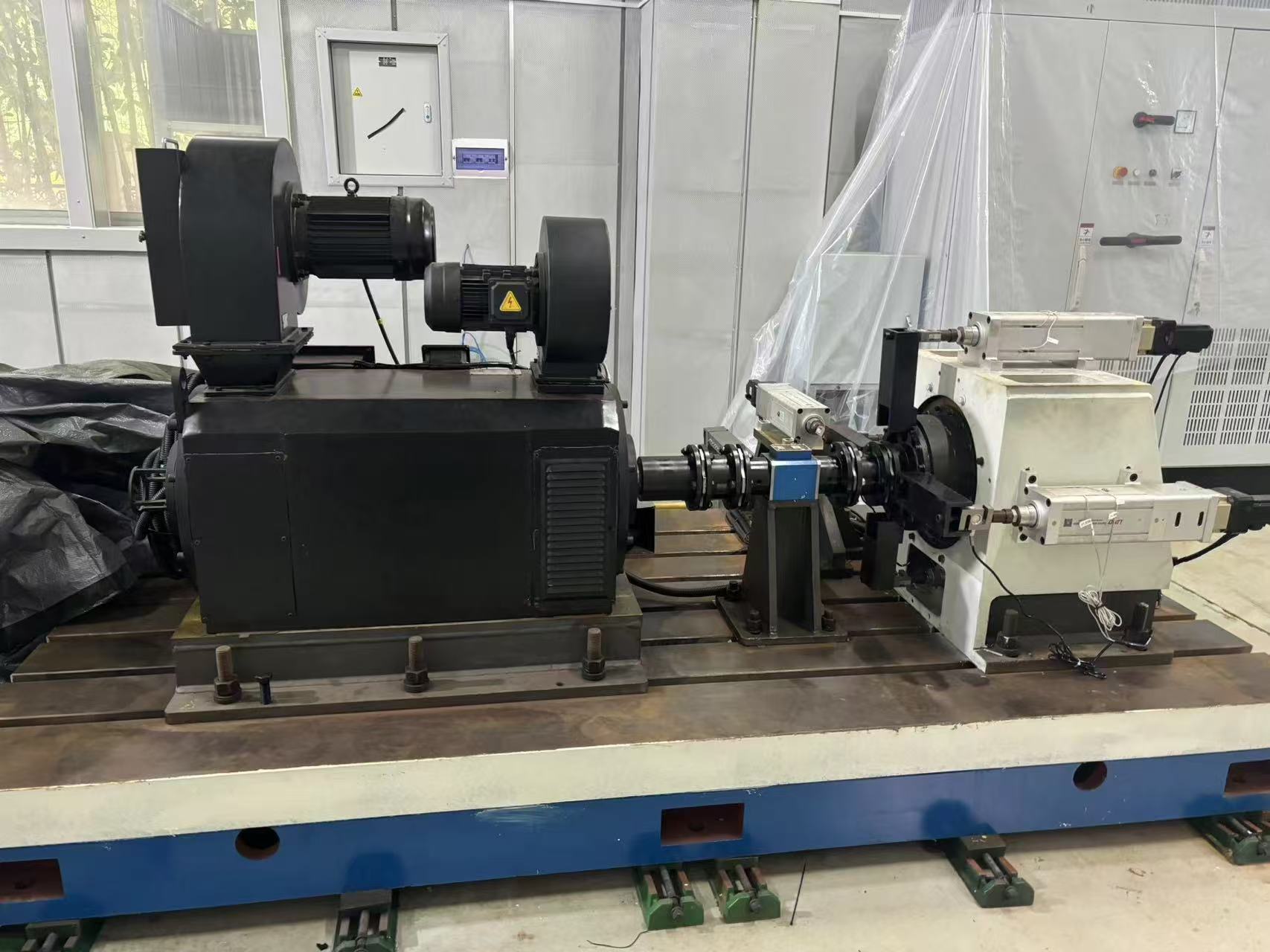
The base-mounted torque meter is fixed on the machine equipment's base, through which power is transmitted. During operation, the power input causes the elastic elements inside the torque meter to deform proportionally to the torque. This deformation is converted into an electrical signal by strain gauges or sensors. Meanwhile, a speed sensor collects rotational speed information. The raw electrical signals are processed by a conditioning circuit and then transmitted to the data acquisition and display device, which real-time presents parameters like torque, speed, and calculated power for monitoring the equipment's power transmission status.
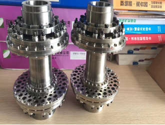
High-speed couplings connect two high-speed rotating shafts with rigid or elastic elements, compensating for deviations from errors and deformation to ensure power transmission. Rigid couplings firmly link well-aligned shafts with precision structures, while elastic ones use materials like rubber or metal diaphragms to buffer vibrations, absorb shocks, allow offsets, and maintain shaft system stability. They are crucial in aerospace, steam turbines, and other high-speed, high-reliability fields.
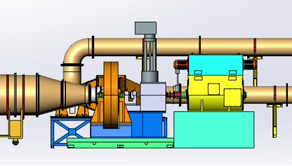
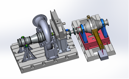
The high-pressure turbine test rig generates high-pressure airflow through the air supply system, which is delivered to the test section via pipelines to simulate the high-pressure environment of the turbine in actual operation. Meanwhile, the temperature control system regulates the airflow temperature, and sensors are used to monitor the turbine's aerodynamic parameters, structural stress, and heat exchange in real time. The control system adjusts the operating conditions to test the turbine's performance under high pressure, providing data support for turbine design optimization.
The testing system simulates flight conditions to assess motor performance. A power supply module mimics the aircraft's power environment by providing variable voltage and frequency. Load equipment replicates in - flight resistances. High - precision sensors gather real - time data on speed, torque, current, voltage, and temperature. The data module analyzes this information against preset standards to check performance compliance. The control system adjusts test conditions as needed, ensuring accurate evaluation of the motor's reliability, efficiency, and stability for new energy aircraft.
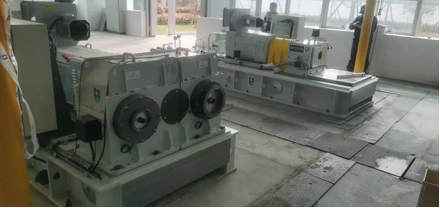
When in operation, the high - speed gearbox with an integrated high - speed torque meter has its input shaft receive power and transfer it to the output shaft via a gear set. Through precise tooth profile design and structural layout, the gearbox alters speed and torque to suit equipment needs. Simultaneously, the torque meter monitors torque changes during transmission. Its sensors convert torque signals to electrical ones, sending them to the control system. This enables the system to analyze, adjust the gearbox's operation for stable, efficient performance across various conditions, and offers data for maintenance and optimization.
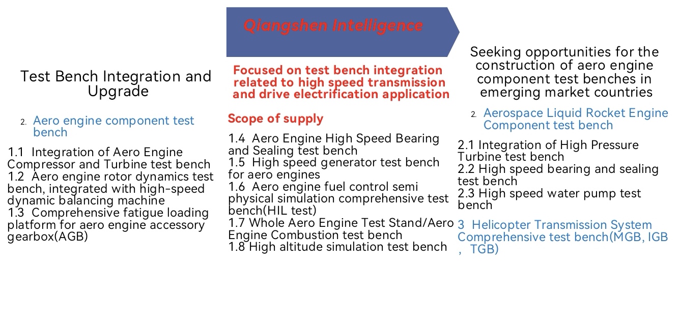
1.1 Integration of Aero Engine Compressor and Turbine test bench 1.2 Aero engine rotor dynamics test bench, integrated with high-speed dynamic balancing machine 1.3 Comprehensive fatigue loading platform for aero engine accessory gearbox(AGB) 1.4 Aero Engine High Speed Bearing and Sealing test bench 1.5 High speed generator test bench for aero engines 1.6 Aero engine fuel control semi physical simulation comprehensive test bench(HIL test) 1.7 Whole Aero Engine Test Stand/Aero Engine Combustion test bench 1.8 High altitude simulation test bench

I. Integration of High Pressure Turbine test bench II. High speed bearing and sealing test bench III. High speed water pump test bench

The helicopter transmission system comprehensive test bench covers test devices for the main, intermediate, and tail gearboxes. The main gearbox links the engine and main rotor, reducing speed and increasing torque. The intermediate gearbox connects the main and tail gearboxes, adjusting speed. The tail gearbox at the helicopter's tail modifies speed and torque to drive the tail rotor, balancing the main rotor's anti-torque for stability. The bench simulates real flight conditions to test and verify the components' performance.
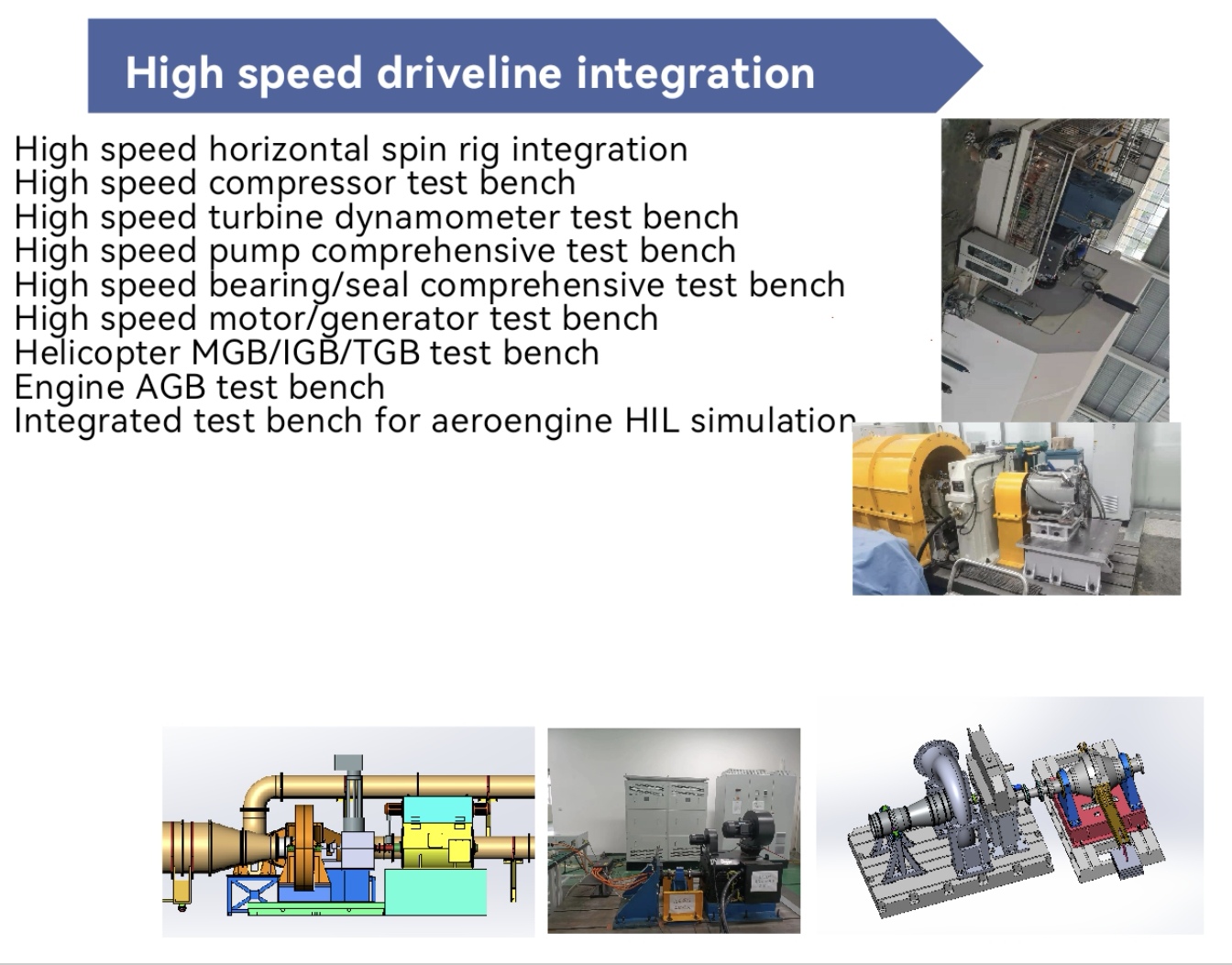
1.High speed horizontal spin rig integration 2.High speed compressor test bench 3.High speed turbine dynamometer test bench 4.High speed pump comprehensive test bench 5.High speed bearing/seal comprehensive test bench 6.High speed motor/generator test bench 7.Helicopter MGB/IGB/TGB test bench 8.Engine AGB test bench 9.Integrated test bench for aeroengine HIL simulation
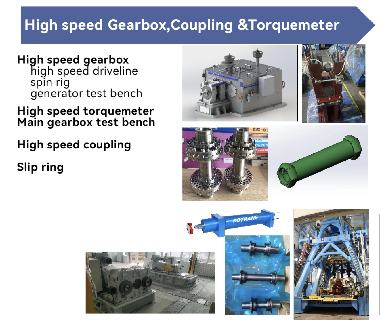
1.High speed gearbox 1.1high speed driveline 1.2spin rig 1.3generator test bench 2.High speed torquemeter 3.Main gearbox test bench 4.High speed coupling 5.Slip ring
1.1 Integration of Gas turbine Engine Compressor and Turbine test bench 1 .2 Gas turbine engine rotor dynamics test bench, integrated with high-speed dynamic balancing machine 1.3 Comprehensive fatigue loading platform for Gas turbine engine accessory casings 1.4 Gas turbine Engine High Speed Bearing and Sealing test bench 1.5 High speed generator test bench for Gas turbine engines 1.6 Gas turbine engine fuel control semi physical simulation comprehensive test bench 1.7 Gas turbine Engine Test Stand/Gas turbine Engine Combustion test bench
2.1 Integration of High Pressure Turbine test bench 2.2 High speed bearing and sealing test bench 2.3 High speed water pump test bench
The integrated test bench for helicopter transmission systems (main, intermediate, and tail reducers) uses a power unit to simulate engine output torque. The torque is transmitted to the main reducer, which reduces speed and increases torque to drive the main rotor. The intermediate reducer transfers power and adjusts the transmission path between the main and tail reducers, while the tail reducer further reduces speed to drive the tail rotor. The test bench monitors parameters like rotation speed and torque via sensors, and uses a loading system to simulate various flight conditions, thereby evaluating the performance and reliability of the transmission system.
Mobile Applications